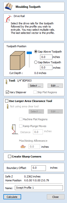
Fluting Toolpath

Fluting Toolpaths machine along vectors while varying the depth of the tool, creating extremely efficient machined decorative patterns.
This toolpath is similar to the option to Profile On a selected vector. The difference is the toolpath at the end of each vector can be ramped to taper the cut. This can be used for cutting standard woodworking Flutes or can be used for artistic engraving and marking effects with other types of artwork. In this section the options on the form will be covered along with some examples of the use for different applications.
Standard Straight Flutes
One of the most common applications for Fluting is straight decorative details using a large radius Ball nose tool for columns and posts, such as the one shown in the image below.
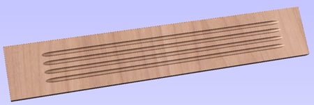
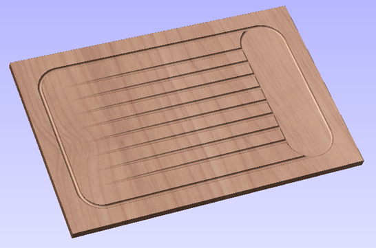
Another good application for straight flutes is the markings on a draining board (for Solid Surface fabricators) or on a cutting block (for carving meat) such as the one shown below, sloping down to allow liquid to be directed.
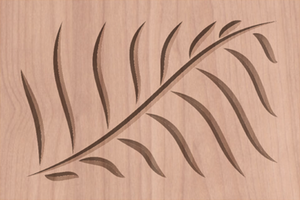
Decorative Artistic Designs
The fluting can be used to produce some interesting effects with artistic and decorative applications. The abstract leaf pattern below left was cut with a V-Bit into a flat surface using single vector lines.
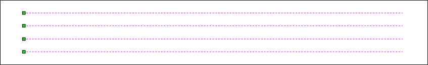
When the Fluting Toolpath form is open, the selected vectors will have their start points indicated in the 2D View by solid square green nodes, this is important as it will determine which end the ramps are added depending on what options are chosen on the form. An image of this is shown below where all the start points are to the left end of the selected vectors.
If you need to move the start points, go into node editing mode (press N on the keyboard or select the node editing icon in the Edit Vectors section on the left tab).
Select the vector you want to change the start point Move the cursor over the end you want to be the new start point Press P on the keyboard or Right Click and select Make Start Point from the pop-up menu. Exit node edit mode (press N again) Reselect all the vectors you want to flute
The fields on the form are as follows.

Cutting Depths
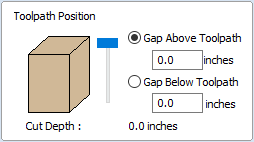
Start Depth (D)
This specifies the depth at which the Fluting toolpath is calculated. When cutting directly into the surface of a job the Start Depth will usually be 0. If machining into the bottom of an existing pocket or stepped region, the depth of the pocket/step that you are starting from must be entered.
Flute Depth
This is the depth of the Fluting toolpath relative to the Start Depth; the total depth will be the combination of the Start and Flute Depth.Tool
Clicking the button opens the Tool Database from which the required tool can be selected. See the section on The Tool Database for more information on this. Clicking the button opens the Edit Tool form which allows the cutting parameters for the selected tool to be modified, without changing the master information in the database.

Flute Type
Ramp over complete length
Checking ✓ this option means the tool will ramp over the whole length of the toolpath. At the start of the selected vector/s it will be at the Start Depth and at the end of the selected vector/s it will have cut down to the Fluting Depth.
Ramp at Start
Checking ✓ this option means the tool will ramp down only at the start of the vectors to the Fluting Depth. The distance of this ramp can be specified using the Ramp Length or Ramp % options.
Ramp at Start and End
Checking ✓ this option means the tool will ramp down at the start of the vectors then will ramp up again at the end of the vectors. The distance of these ramps can be specified using the Ramp Length or Ramp % options.
Ramp Length
Checking ✓ this option means that the length of the ramp can be set to an exact distance entered into the box. The ramp distance is measured from the start and the end of the vector/s depending what Flute Type you have selected. If the distance entered is greater than the possible length of the ramp then the maximum length will be used, this would be the same as choosing Ramp over complete length. When you choose Ramp at Start it is possible to specify a ramp length which is up to the length of the vector/s. When Ramp at Start and End is checked, ✓ the maximum length possible would be half way along the vector/s as after that it would start to ramp up again.
Ramp %
Checking ✓ this option means that the length of the ramp can be specified as a percentage of the maximum possible ramp length (controlled by the length of the selected vector/s and chosen Flute Type). When you use this with Ramp at Start selected then 100% would be the whole length of the selected vector/s, the ramp length would be a percentage of this distance for each one. When you use this with Ramp at Start and End then 100% would be the half length of any of the selected vector/s. The ramp length would be a percentage of this half-length. In this situation using a 50% value would give you a Ramp from the start which was ¼ of the vector length and a ramp from the end which was also ¼ of the vector length.

Ramp Type
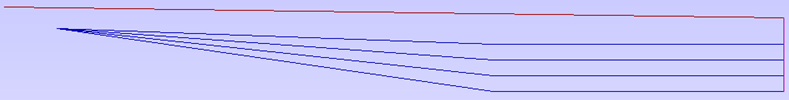
Linear
Selecting the Linear type will create a ramp which is a diagonal line (following the vector) from the Start Depth to the Flute Depth. Below you can see a Linear Ramp Type shown from the side. This ramp is set to only ramp from the start and to go 50% of the flute length.
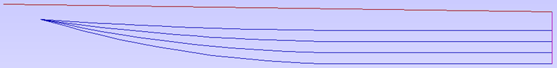
Smooth
Selecting the Smooth type will create a curved ramp (following the vector) from the Start Depth to the Flute Depth; this will smoothly transition from the ramp into the full depth of cut. You can see an example of this shown in the image below.
General Toolpath Settings
This section of the toolpath form is common to a number of toolpath strategies.
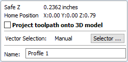
Safe Z
The height above the job at which it is safe to move the cutter at rapid / max feed rate. This dimension can be changed by opening the Material Setup form.
Home Position
Position from and to that the tool will travel before and after machining. This dimension can be changed by opening the Material Setup form.
Project toolpath onto 3D Model
This option is only available if a 3D model has been defined. If this option is checked, ✓ after the toolpath has been calculated, it will be projected (or 'dropped') down in Z onto the surface of the 3D model. The depth of the original toolpath below the surface of the material will be used as the projected depth below the surface of the model.
Vector Selection
This area of the toolpath page allows you to automatically select vectors to machine using the vector's properties or position. It is also the method by which you can create Toolpath Templates to re-use your toolpath settings on similar projects in the future. For more information, see the sections Vector Selector and Advanced Toolpath Templates.
Name
The name of the toolpath can be entered or the default name can be used.